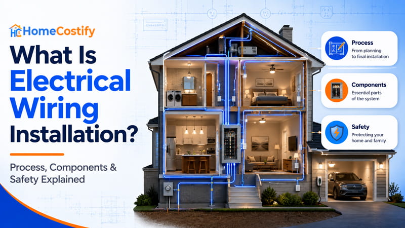
Electricity reaches dozens of points inside a house every day, yet very little attention goes to what carries that power from its source. Electrical wiring installation creates a safe distribution route beginning at the service entrance and extending across each outlet, switch, light fixture, and permanently connected appliance.
Far more than cable placement, that work establishes an electrical circuit network built to deliver stable power across normal household use.
Every outlet responds because electricity follows a planned route instead of random wire runs. Within an electrical wiring installation, electrical energy moves from its source toward each point of use through a controlled distribution network, keeping supply aligned with circuit demand instead of uncontrolled flow.
Stable power depends on continuous distribution, not cable placement alone. Decisions made during construction or major renovation continue influencing electrical service long after the house is occupied.
Each part of that journey builds a clearer picture of how electricity reaches every room across years of regular use.
How Residential Electrical Wiring Installation Works
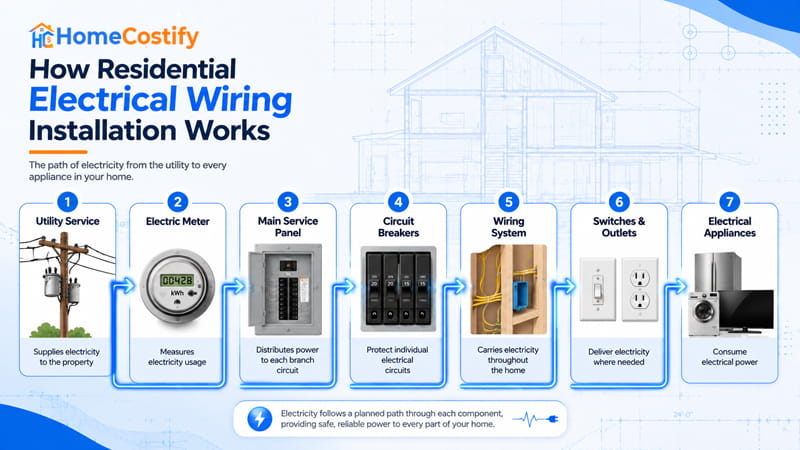
A residential electrical wiring installation operates as one connected electrical network. Every circuit receives electricity through a defined sequence from utility service to each destination.
What Is Electrical Wiring Installation?
Electrical wiring installation builds the complete network carrying electricity throughout a house. Utility service supplies incoming electricity before conductors carry it toward every required location.
Distribution equipment directs electrical flow across outlets, switches, lighting, and permanently connected appliances. Cable installation represents only one part of that work.
Each circuit receives electricity according to its expected load. Balanced distribution keeps electrical demand within planned circuit capacity during everyday operation.
How Electricity Travels Through a Home
Electricity moves through a fixed sequence before reaching any connected load. Every location depends on upstream equipment operating in the correct order.
| Electrical Path | Purpose |
|---|---|
| Utility Service | Supplies electricity to the property |
| Electric Meter | Measures electricity usage |
| Electrical Service Panel | Distributes power to each branch circuit |
| Circuit Breakers | Protect individual electrical circuits |
| Wiring System | Carries electricity throughout the home |
| Switches & Outlets | Deliver electricity where needed |
| Electrical Appliances | Consume electrical power |
Utility service supplies incoming electricity first. The electric meter records total consumption. The main service panel sends electricity into branch circuits.
Conductors carry electricity toward switches, outlets, lighting, and permanently connected equipment. Electrical appliances finally consume that energy.
A fault near the beginning interrupts every downstream connection. Early distribution decisions influence every electrical circuit served beyond that location.
Components of a Residential Electrical Wiring System
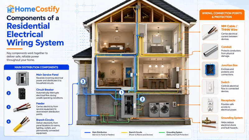
A home electrical wiring installation combines multiple component categories with different responsibilities. Incoming electricity reaches household loads only after distribution, protection, control, and connection functions operate in sequence.
Main Distribution Components
Electrical distribution starts inside a main service panel, commonly called a load center. Incoming supply arrives at one location before branching into separate electrical paths serving household demand.
Power does not travel directly from service equipment to outlets. A feeder transfers supply toward distribution points, where branch circuits continue service into lighting, receptacles, switches, and permanently connected equipment. Distribution expands step by step without one pathway carrying every load.
Protection follows that distribution structure. Every circuit breaker monitors one branch circuit instead of supervising all electrical loads. Fault conditions stay confined to one circuit, leaving unaffected areas available for normal operation.
Distribution works because responsibilities stay separated. Panel equipment divides incoming supply. Feeders extend distribution. Branch circuits reach electrical loads. Circuit breakers guard assigned circuits.
Main distribution components
- Main service panel — Receives incoming electrical power and distributes it to household circuits.
- Circuit breaker — Automatically interrupts electrical flow during unsafe operating conditions.
- Feeder — Carries electricity from service equipment to downstream distribution points.
- Branch circuits — Deliver electricity from panel locations to rooms, lighting, outlets, and permanently connected equipment.
Relationships between electrical wiring components determine electrical distribution across household circuits.
Wiring, Connection Points, and Protection
Distribution reaches household loads through conductors, enclosed connections, control devices, and grounding equipment. Removing one category interrupts electrical continuity, even when remaining components stay intact.
House electrical wiring commonly uses NM cable or THHN wire. Electrical wire specifications identify conductor properties for different wiring methods. Conduit protects conductors against physical damage. An electrical box encloses wire connections. Junction box locations contain splices inside protected enclosures. Cable clamp hardware secures cable entry into electrical boxes.
Control begins where electricity reaches occupied spaces. Switches interrupt electrical flow serving connected loads. Receptacles supply plug-connected equipment without exposing energized conductors during normal use.
Fault current follows a separate path. Grounding conductor routes unwanted current away from exposed metal parts. Bonding joins conductive metal surfaces into one fault path. Neutral bus terminates grounded conductors. Ground bus terminates equipment grounding conductors.
| Component | Primary Function |
|---|---|
| NM Cable / THHN Wire | Carries electrical current between devices |
| Conduit | Protects conductors from physical damage |
| Junction Box | Encloses and protects wire connections |
| Switch | Controls electrical flow to connected devices |
| Receptacle | Provides safe access to electrical power |
| Grounding System | Helps reduce electrical shock and fault hazards |
Conductors carry electrical current. Enclosures protect wire connections from accidental contact. Control devices regulate electrical access. Grounding equipment handles fault current. No single component can replace another without affecting electrical distribution.
Removing any one category interrupts the complete electrical path, leaving the system unable to operate as intended.
Planning a Residential Electrical Wiring Installation
Long before physical work begins, planning determines how a residential electrical wiring installation will support daily living and future expansion. Early decisions shape circuit capacity, electrical distribution, room usage, and long-term reliability inside a home electrical system.
Evaluating Electrical Demand and Circuit Requirements
Planning starts with expected household power consumption. An electrical load estimate identifies normal demand across lighting, appliances, heating, cooling, and everyday equipment. That information forms a load calculation, giving designers a practical reference for future electrical use without relying on guesswork.
Capacity matters long after construction ends. Panel capacity must support current demand without leaving electrical distribution under constant pressure. Planning also reserves space for changing household needs instead of limiting future upgrades.
High-demand equipment receives extra attention during planning. A dedicated circuit separates continuous or heavy electrical loads from general household use. Future electrical demand also enters early decisions.
Electric vehicle chargers, heat pumps, workshops, and home offices increase electrical demand beyond original living requirements. Reserved capacity accommodates those additions without major changes to the original residential electrical wiring installation.
Planning priorities
- Estimated electrical load — Identifies expected household power demand during normal use.
- Panel capacity — Confirms available distribution capacity for planned circuits.
- Dedicated circuits — Reserve electrical supply for higher continuous loads.
- Future expansion — Leaves available capacity for additional equipment and electrical upgrades.
Choosing Wiring Routes and Installation Methods
Cable routes receive attention before framing closes wall cavities. Good wire routing shortens unnecessary cable runs and reaches intended locations without creating difficult access later.
A rough-in wiring layout places future cable paths on construction plans before wall finishes begin. Planning may include PVC conduit or EMT conduit, depending on structural conditions and future accessibility goals.
Routing decisions also consider remodeling possibilities, service access, and room changes years after construction finishes.
| Planning Consideration | Purpose |
|---|---|
| Wire routing | Creates efficient cable paths throughout the home |
| Rough-in layout | Organizes cable locations before walls are finished |
| Conduit or cable path | Protects wiring while supporting future access |
| Accessibility | Allows future servicing and modifications |
| Room layout | Supports convenient placement of outlets, switches, and fixtures |
Accessible routing reduces disruption during later upgrades. Flexible layouts accommodate changing room functions without extensive structural changes.
A home electrical wiring installation gains practical value long after original construction. Expansion becomes simpler when a home electrical wiring installation already includes accessible routing.
Permits, Codes, and Project Preparation
Technical planning covers only part of project preparation. Administrative planning begins before any electrical wiring installation enters construction schedules.
Most projects require a permit before physical work starts. Local authorities review proposed work against an applicable electrical code. An inspection follows later during project execution, not during planning. Timing, documentation, contractor coordination, and scheduling receive attention before construction begins.
Requirements vary between states, counties, cities, and local authorities. Early preparation avoids scheduling conflicts and keeps project documentation ready before electrical wiring installation moves into construction.
How Residential Electrical Wiring Is Installed
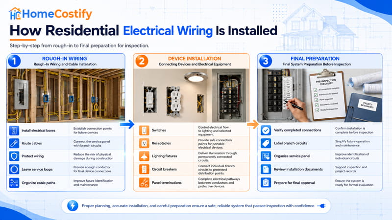
Construction follows a predictable sequence even though house layouts differ. A home electrical wiring installation moves from open framing to completed circuits, giving each stage a clear objective before permanent electrical service enters normal operation.
Rough-In Wiring and Cable Installation
Open framing creates full access to wall cavities, ceilings, and floor assemblies. That stage marks the beginning of rough-in wiring, where permanent cable paths start taking shape across future living spaces. Structural framing guides wire routing, reducing unnecessary cable runs and supporting planned circuit layouts.
An NM cable extends from distribution points toward outlets, switches, lighting locations, and fixed equipment. Each electrical box establishes a permanent connection point, giving future devices an assigned location once wall finishes are complete.
Extra conductor length stays inside each box, leaving sufficient wire for final terminations without stretching conductors.
A cable clamp secures wiring where required, reducing unnecessary movement as construction continues. Cable paths stay separated from activities that could create physical damage before interior finishes cover framing.
By this stage, a home electrical wiring installation already contains its permanent distribution framework, even though electrical devices have not yet been installed. That framework continues into the remaining electrical wiring installation process.
| Rough-In Activity | Purpose |
|---|---|
| Install electrical boxes | Establish connection points for future devices |
| Route cables | Connect the service panel with branch circuits |
| Protect wiring | Reduce the risk of physical damage during construction |
| Leave service loops | Provide enough conductor for final device connections |
| Organize cable paths | Improve future identification and maintenance |
Connecting Devices and Electrical Equipment
Wall finishes close structural spaces, turning rough cable runs into usable electrical pathways. Conductors placed during rough-in now receive permanent terminations, completing usable pathways across a residential electrical wiring installation.
Each receptacle, switch, and lighting fixture occupies a planned location established during earlier work. Inside distribution equipment, every branch circuit reaches its assigned circuit breaker, preserving circuit organization established during project planning.
Conductors terminate on both a neutral bus and a ground bus, completing distribution paths required for normal operation.
Every planned connection now forms part of a continuous distribution network. Electrical flow follows circuit layouts established during planning, carrying power from distribution equipment to each point of use.
A home electrical wiring installation reaches functional completion across a residential electrical wiring installation.
Connected equipment
- Switches — Control electrical flow to lighting and selected equipment.
- Receptacles — Provide safe connection points for portable electrical devices.
- Lighting fixtures — Deliver illumination through permanently connected circuits.
- Circuit breakers — Connect individual branch circuits to protected distribution points.
- Panel terminations — Complete electrical pathways between conductors and protective devices.
Final System Preparation Before Inspection
Physical installation concludes before normal electrical use begins. Project organization, documentation, and final verification prepare completed work for formal evaluation.
Completed connections receive a final visual verification, confirming that planned devices and conductors occupy intended locations. Each branch circuit receives clear identification, making future operation simpler for homeowners and service professionals.
Circuit labels correspond with positions inside the main service panel, reducing confusion after occupancy.
Project records receive another review alongside scheduling and contractor coordination. Documentation requirements vary by jurisdiction, project scope, and electrician labour rates, since contractor workflow and project organization differ across installations without affecting installation quality.
This preparation supports an upcoming inspection without entering inspection procedures.
| Preparation Step | Purpose |
|---|---|
| Verify completed connections | Confirm installation is complete before inspection |
| Label branch circuits | Simplify future operation and maintenance |
| Organize service panel | Improve identification of individual circuits |
| Review installation documents | Support inspection and project records |
| Prepare for final approval | Ensure the system is ready for formal evaluation |
By this point, physical installation is complete and project documentation is organized. Formal evaluation follows before the system enters normal service.
Testing and Inspecting an Electrical Wiring Installation
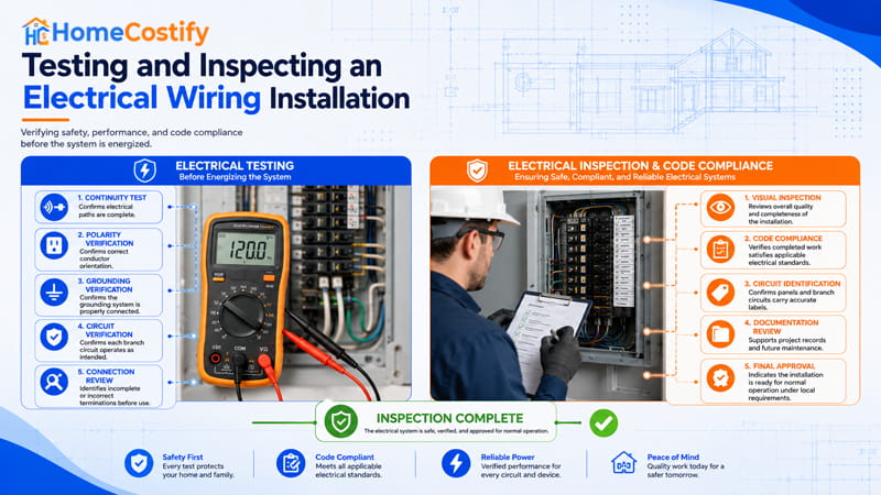
A completed electrical system still requires verification before normal operation begins. Testing and inspection confirm that circuits function as intended, protective measures are complete, and the finished electrical wiring installation satisfies applicable safety requirements.
Electrical Testing Before Energizing the System
Electrical verification confirms that completed work matches the original circuit design. Every branch circuit undergoes a series of checks that examine conductor continuity, circuit arrangement, grounding paths, and completed terminations before normal electrical use begins.
A continuity test confirms that intended electrical paths remain complete from one termination point to another. Polarity verification confirms that conductors occupy their intended positions, preventing circuit arrangements that differ from planned layouts.
Grounding verification confirms that protective grounding paths extend across completed circuits without interruption.
Testing also confirms circuit integrity across completed connections. Conductors, grounding paths, protective devices, and terminations function as one operating network instead of separate parts.
A completed residential electrical wiring installation reaches regular service only after those verification results support normal operation.
| Test | Purpose |
|---|---|
| Continuity Test | Confirms electrical paths are complete |
| Polarity Verification | Confirms correct conductor orientation |
| Grounding Verification | Confirms the grounding system is properly connected |
| Circuit Verification | Confirms each branch circuit operates as intended |
| Connection Review | Identifies incomplete or incorrect terminations before use |
Electrical Inspection and Code Compliance
Inspection evaluates completed workmanship, installation quality, project documentation, and compliance with an applicable electrical code before normal occupancy.
A visual inspection compares completed work with approved project requirements. Inspectors review device placement, conductor identification, labeling, and installation quality.
Clear circuit identification inside the main service panel supports future service work and confirms that completed layouts match project documentation.
Inspection requirements vary across local jurisdictions, even though core safety principles remain consistent. Scheduling, documentation, and review timelines sometimes influence overall project coordination and contribute to electrical work cost without changing construction quality.
Once approval is issued, the completed installation satisfies the project requirements established for that work.
Inspection overview
- Visual inspection — Reviews overall quality and completeness of the installation.
- Code compliance — Verifies completed work satisfies applicable electrical standards.
- Circuit identification — Confirms panels and branch circuits carry accurate labels.
- Documentation review — Supports project records and future maintenance.
- Final approval — Indicates the installation is ready for normal operation under local requirements.
Electrical Wiring Safety Best Practices
Electrical safety begins with thoughtful system design and protective equipment. A home electrical wiring installation combines multiple safety features that reduce electrical hazards across normal household use and changing electrical demands over time.
Built-In Protection for Modern Electrical Systems
Modern residential electrical systems rely on overlapping protective features instead of a single safeguard. Each device addresses a different type of electrical fault, creating multiple layers of protection across a home electrical wiring installation.
Overcurrent protection limits electrical current when abnormal conditions develop, reducing damage to conductors and electrical equipment.
AFCI detects electrical arcing associated with wiring faults that could increase fire risk. GFCI responds to abnormal current flow associated with electric shock hazards in suitable locations.
Surge protection reduces damage from unexpected voltage spikes affecting electronic equipment and household appliances. A properly installed grounding conductor directs fault current toward a controlled path, supporting protective devices during abnormal electrical conditions.
Because every protective device responds to a different fault, one failure does not leave the entire system without protection.
| Protective Feature | Primary Purpose |
|---|---|
| Circuit Breakers | Interrupt unsafe electrical current |
| AFCI | Helps reduce fire risks caused by electrical arcing |
| GFCI | Helps reduce electric shock hazards |
| Surge Protection | Reduces damage from voltage spikes |
| Grounding System | Provides a safe path for fault current |
Keeping an Electrical Wiring System Reliable Over Time
Household electrical demand rarely stays unchanged across decades of occupancy. New appliances, home additions, remodeling projects, and changing lifestyles introduce different demands on a residential electrical wiring installation without altering its original design.
Periodic evaluation identifies visible changes that deserve professional attention. Physical damage, discoloration, loose device covers, or altered circuit labeling indicate that another inspection may be appropriate.
Growing electrical load from vehicle charging, workshop equipment, or major HVAC upgrades also justifies another review of system capacity and branch circuit organization.
Large remodeling projects frequently introduce new electrical requirements. Updated room layouts, additional appliances, and expanded living areas can change circuit usage patterns established during original construction.
Early evaluation sometimes identifies conditions before they develop into larger projects that increase future electrical wiring cost.
Good long-term practices
- Observe visible signs of damage or wear.
- Reassess the system after major remodeling projects.
- Consider additional evaluation when electrical demand increases significantly.
- Keep circuit identification updated after modifications.
- Arrange professional inspections when major system changes occur.
Timely evaluation keeps a residential electrical wiring installation aligned with changing household electrical demand. Another electrical wiring installation review may be appropriate after significant electrical upgrades or major remodeling.
Conclusion
Every light, outlet, and permanently connected appliance reflects planning completed long before the house is occupied. Circuit planning, cable routing, equipment installation, testing, and inspection all contribute to a reliable home electrical system, with each branch circuit forming part of a larger distribution network.
Homeowners planning new construction or remodeling often face the same decisions discussed throughout this installation process, from circuit planning to final inspection.
A properly executed electrical wiring installation leaves the finished home with a dependable electrical system ready for everyday living and capable of supporting changing household electrical demands over time. years ahead.
FAQs About Electrical Wiring Installation
How long does an electrical wiring installation take?
Project duration depends on house size, construction progress, system complexity, and scheduling. Every electrical wiring installation follows a different timeline based on project conditions.
Can a home electrical wiring installation be expanded later?
Yes. A home electrical wiring installation can usually expand when panel capacity, circuit design, and future electrical demand support additional circuits or equipment.
What is the difference between electrical wiring installation and rewiring?
New installation builds an electrical system from the beginning. Rewiring replaces or upgrades existing wiring. Homeowners comparing replacement projects can explore cost to rewire a house separately.
Why are inspections required after electrical wiring installation?
Inspections confirm completed work satisfies applicable safety requirements and project standards before an electrical wiring installation enters normal service.
Does electrical installation cost include inspections?
It depends on project scope and contractor agreements. Some proposals include inspection fees, whereas others list them separately within the electrical installation cost.